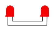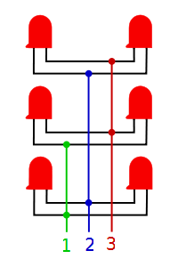


Making small charlieplex arrays is fairly simple, really. It starts with number of sub-assemblies of two LEDs each. From there these sub-assemblers are wired into the final harness one at a time. For each step in this process you only have to deal with one sub-assembly and two wires. The only tricky part is figuring out which two wires to use. With a good plan you can have a finished charlieplex array in a short time with a minimum of fuss.

The first step is building the sub assemblies. These are build from two LEDs and a little wire for each assembly. I like to start by soldering length of wire to each lead of all of the LEDs. At this stage I like to insulate the solder joints where the wires are connected to the LEDs. It is easy to put heat-shrink tubing on the unconnected wires. The next step is to strip the free ends of the wires and make assemblies of two of the wire-LED groups. These need to be put together anode to cathode. This is easier then it sounds. the trick is to test each assembly as you make them. The testing is done using a power-supply and a current-limiting resistor that can safely light up one of the LEDs you are using. As you twist the wires together test each assembly. It doesn't matter which way the wires are attached. Only one LED should light when they are connected. Try attaching the wires first one way and then reverse them. One LED should light both ways. If the both light at one time then you have the anodes together and the cathodes together. Reverse the way the wires are attached and they should light one at a time. If an LED does not light at all it might have been damaged on the first step. Don't solder the twisted wires together yet, that is done in the next step.

The next step is to attach the first two lead wires to the assembly. These are marked 1 and 2 in the final assembly picture. For lead 1 take two short wires and attach them to one of the twisted wire pairs of the first group of LEDs. Solder them and place one of them pointing up and the other pointing down. For lead 2 use a long wire and a short one and attach and solder them to the second pair of the same group. Place the long one pointing up and the short one pointing down. Now put another of the LED assemblies where the wire from lead one is point up. Attach and solder this one wire to a twisted pair in LED assembly. Now take a long wire and a short one to start lead 3. These are attached to the second twisted wire pair. After they are soldered place the short one pointing up and the long one pointing down. The last of the LED assemblies are placed next. Attach the long wire coming from lead 1 to one of the twisted pair of wires and the short wire from lead 3 to the other. When these connections are soldered it is time to test the the complete assembly.
The charlieplex array is almost finished. The next step is testing. Using the test rig from before, attach each wire to each of the terminals of the test rig. An LED should light up each time. Here is a table that shows the steps. One LED should light up for each of these combinations.
| Leads | |||
|---|---|---|---|
| LED | 1 | 2 | 3 |
| 0 | + | - | |
| 1 | - | + | |
| 2 | + | - | |
| 3 | - | + | |
| 4 | + | - | |
| 5 | - | + | |
The current-limiting resisters are a little different for a charlieplex array. Because of the way the LEDs are lit there has to be a resister on each of the three leads. Each of these resistors is half of the resistance needed to light a single LED. This works because when one lead is high and the other low there are two resistors in the circuit that lights the LED.
A good last step is to insulate each of the places where wires or resistors were soldered together. With everything assembled and tested your charlieplex array is ready to use. Go back to the Structured Charlieplexing page to learn more about using your new array.